
Die HiQSDR Medium Power PA mit 8-10 Watt PEP Leistung lässt sich direkt in die Preselektorbaugruppe
einstecken. Durch ihre universelle Bauweise ist aber eine Verwendung als separate Treiber-PA oder auch
als kleine QRP-Endstufe unproblematisch für beliebig andere Anwendungen möglich.
Der Aufbau ist dabei so gestaltet, dass alle signalführenden Leitungen auf der Oberseite der Platine
geführt werden. So kann die gesamte Rückseite als durchgängige Massefläche und - mit einer Kühlfläche versehen - zum Abtransport der Verlustwärme genutzt werden.
Die HiQSDR MPPA ist sehr universell einsetzbar. Die zweifachen Gegentaktstufen der MPPA ergeben eine Verstärkung von >40dB, so dass auch SDR-Transceiver oder Signalquellen ab 0dBm Ausgangsleistung die volle Leistung von ca. 10 Watt PEP erzeugen.
Die MPPA ist ein Breitband-Linearverstärker Klasse A und kann im gesamten Kurzwellenbereich von
1 MHz bis 62 MHz betrieben werden. Die Ein und Ausgangsimpedanz ist jeweils 50 Ohm.
Auch Kurzschlüsse und offener Betrieb verträgt die MPPA kurzzeitig ohne Beschädigung, dabei ist aber auf ausreichende Kühlung zu achten!
Die Versorgung erfolgt aus 12..13.8 Volt DC, max. 2.5 Ampere. Die MPPA hat am Eingang ein frei
bestückbares Pi-Dämpfundglied, um die Eingangsleistung bei höheren Treiberleistungen frei anpassen zu können. Für den Betrieb am HiQSDR ist hier ein 6dB-Pad notwendig. (2 x 150R, 1 x 39R)
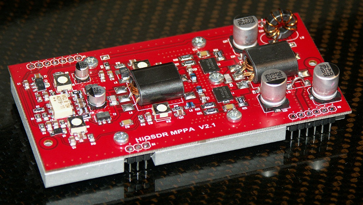
Sowohl als Treiber als auch als "Endstufe" wurden modernste HF-Feldeffekttransistoren von MITSUBISHI, als Treiber 2x RD01MUS und in der zweiten Stufe 2x RD07VS1 eingesetzt.
Das Design der MPPA-Baugruppe wurde von DL2EWN optimiert und vermessen.
Für seine Hilfe möchten wir uns ausdrücklich bedanken!
The HiQSDR Medium Power PA with an output PEP of 8-10 Watts PEP can be directly plugged into the
HiQSDR Preselector Board. The HiQSDR MPPA is universally designed and can be used as separate driver
for bigger Amplifiers as well as QRP PA.
The Board is so designed, that all signal traces are on TOP of the PCB. The Bottom of PCB is completely
grounded and can be mounted directly to a heatsink or a Heatspreader to dissipate the exess heat.
The HiQSDR MPPA is very flexible. The high gain of the dual staged push-pull amplifier design has a gain
of 40dB and allows input signals as low as 0dB to produce up to 10 Watts PEP.
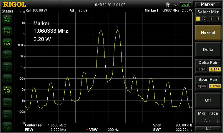
The IP3 of the Amplifier is excellent: at 7.1MHz is the IP3 around -41dBc (!).
The MPPA is a broadband, highly linear amplifer and allows operation from 1 MHz up to 62 MHz.
The input ad output impedance ist 50 Ohm. The MPPA is save against shorts and open output for a
limited time, but pay attention for a good cooling!
The power supply is 12..13.8 Volt DC, max. 2.5 Amps. In both push-pull stages, modern RF field-effect transitors from Hitachi are used, in the driver stage 2 x RD01MUS2 and for the second stage
2x RD07MVS1 types.
The MPPA is optimized by DL2EWN, thank you for your work, time and effort!
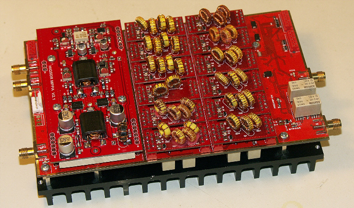
Die MPPA, eingebaut in den HiQSDR-Preselektor :
MPPA plugged into HiQSDR Preselector board :
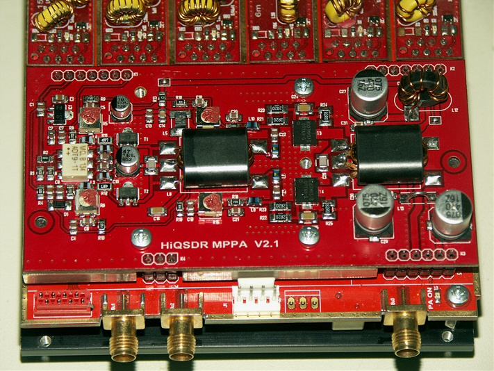
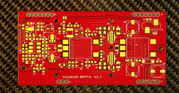
Die MPPA PLatine Version 2.1, Bestückseite. Material FR4, 1mm, vergoldet:
MPPA PCB , Version 2.1, TOPside. Material: FR4 1mm, gold plated:
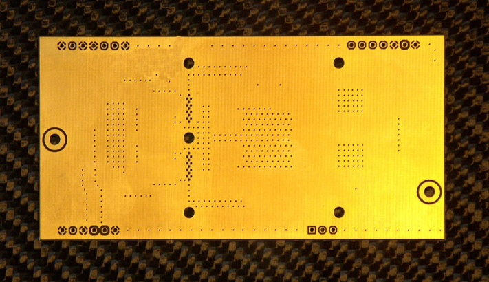
Die MPPA PLatine Version 2.1, Rückseite, komplett gold metallisiert, Massefläche mit Kühldurckkontaktierungen:
MPPA PCB , Version 2.1, BOTTOM, complete gold plated for cooling/GND thru-holes:
Einige Messungen der MPPA, IMD3 < -40dBc, bei ca. 8.8 Watt PEP (2.2Watt * 4 (6dB) = 8.8Watt PEP)
(Messungen und Screenshots von DL2EWN)
Some measurements on MPPA: IMD3 < -40dBc, at 8.8Watt PEP (2.2W * 4 (6dB) = 8.8W PEP)
(measurements and screenshots from DL2EWN)
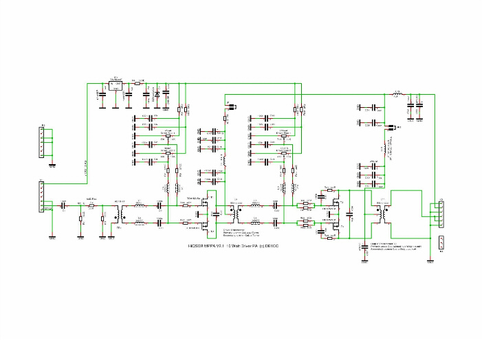
Die Schaltung der MPPA:
The MPPA Circuit Diagram:
(Anklicken zum Vergrößern)
(click to enlarge)
Die Stückliste bitte hier anklicken (PDF):
For BOM (bill of material) please click here (PDF):
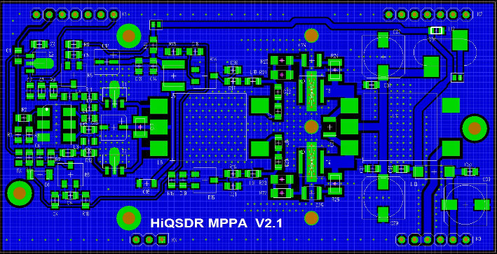
Das Platinenlayout:
The PCB Layout:
Kühlkonzept der MPPA:
Um die Verlustwärme der PA möglichst gut abzutransportieren, ist die Leiterplatte aus nur 1 mm dickem FR4 Platinenmaterial gefertigt. Unter und um die Leistungstransistoren sind im Layout wärmeabführende Duchkontaktierungen vorgesehen. Die Leiterplatte wird auf den Heatspreader (Wärmeverteiler) aufgeschraubt und die beiden Endstufentransistoren DB07MVS1 werden mit einer Druckbrücke auf die Platine bzw.Kühlfläche gedrückt. Zwischen Leiterplatte und Heatspreader sollte dünn (!) ein wärmekoppelndes Material eingebracht werden. Das kann Wärmeleitpaste sein, besser aber ist eine Wärmeleitfolie mit möglichst niedrigem Wärmeleitwiderstand. Am besten geeignet und bewährt hat sich eine 0.2mm Grafitfolie, die einfach mit dem Messer oder Schere entsprechend zugeschnitten wird.
Die Graphitfolie ist weich und formt sich allen kleinen Unebenheiten an. Graphit leitet zwar, aber da die Unterseite auf Masse liegt ist das eher ein Vorteil.
Wichtig ist natürlich auch, den Kühlblock auf einen ausreichend großem Kühlkörper oder eine kühlende Montageplatte zu schrauben - immerhin müssen bei Vollastbetrieb (RTTY, FM, PSK, WJST usw) etwa 10-12 Watt abtransportiert werden. Der Heatspreader alleine ist kein ausreichender Kühlkörper!
Cooling concept of MPPA:
To transport the excess heat from the MPPA, the PCB is made from a 1mm FR4 material. Below and around the power transistors, plated thru-holes are made to transport the heat from the top of he PCB to the bottom part. Th PCB is screwed to a Heatspreader and the Power FET's RD07MVS1 are pressed to the PCB and the Heatspreader by a massive aluminium bar. Between the Heatspreader and the PCB must a heat transport material used. You can use heat transfer grease or (much better) heat transfer foils. Best heat transfer foil for this application is a pure graphite foil of 0.2mm thickness. This foil is soft and transports the heat very effective. Care must be taken because graphite is conductive, but the bottom side of the MPPA is at ground level so this is not important.
Please keep in mind that the Heatspreader is not a Heatsink! Screw the Heat connection bar at the lower side to a heatsink or a large mounting plate to allow cooling. Please keep also in mind, that you have to dissipate around 10 to 12 Watts of heat, especially if you use CW modes like RTTY, FM, PSK or WSJT.
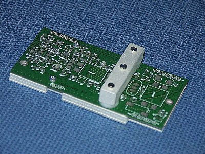
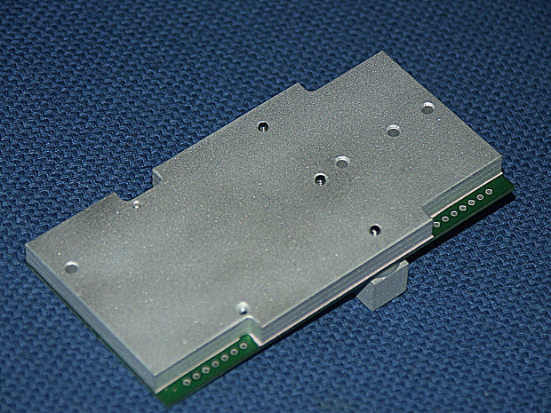
The MPPA PCB with cooling parts (HeatSpreader/Clamp: here a prototype is shown)
MPPA from Backside: Heatspreader, without Heat-Plug
MPPA Heatspreader mit HeatPlug (Wärmeableitung zur Montageplatte)
MPPA Heatspreader with Heatplug (heat transfer to mounting base)
Bestellinformationen finden Sie unter dem Menüpunkt "Bestellungen / Order"
Order informations you will find here: "Bestellungen / Order"